
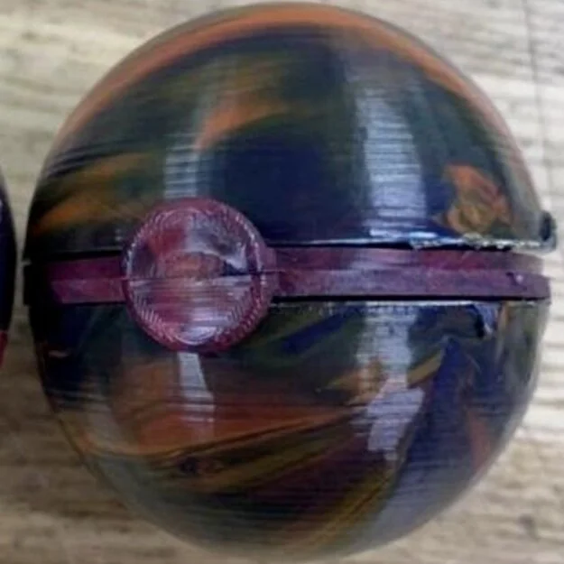
Injection Molded Pokéball Toy

Part & Mold Design
The biggest challenge in the creation of the Pokeball Toy was ensuring the molds were properly designed for the tools and machinery being used. We landed on a design in which two identical half-sphere shells would be joined by pins using a snap fit. This design allows for the easiest assembly of the parts. Each of the parts does not require specific orientation for assembly, due to the design of the ring. Several revisions were performed to rid any undercuts, side action, assembly errors, and other discrepancies between the molds for our parts. Additionally, each of the parts maintains a uniform thickness of 0.125 inches to reduce possibility of defects.

CNC Milling
The molds for the parts were created using programmed g-code in NX, that was then taken to a CNC Mill. For each part, a core and a cavity were required, along with some molds needing extra milling to create runners, sprues, or other essential features. To guarantee an efficient milling process, the team verified that all molds and cavities were properly aligned for assembly, all tools were properly sharpened, axes were programmed properly, and all operations were running smoothly step by step.
Injection Molding
Once the core and cavity for each part were finished, it was time to take them to the injection molding machine. By experimenting with cycle time, mold temperature, nozzle temperature, and nozzle pressure, the team was able to witness first hand the different affects various injection molding factors have on surface finish and deformities. For our particular design, we found that with our relatively thin walls that stretched all around the mold, injecting the plastic at a high temperature and heat allowed the mold to properly fill without defects, while keeping the mold at room temperature cooled the plastic so that it did not contract too greatly.
Load Bearing Bracket Design

Theoretical Design
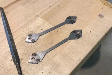
Presented with the challenge to design and build a two member sheet metal bracket that has the capacity to withstand a downward load between 1,500N - 1,800N. The bracket has to consist of two members, AD and BC, that are joint at point D. The final design was selected taking into consideration many aspects, but prioritizing efficiency, strength, cost effectiveness and manufacturability. After deciding on a final design, we began manufacturing and testing brackets to better understand the factors that we wish to optimize. Through a process of manufacturing, testing, and analysis our group was able to manufacture a bracket that adheres to the criteria set forth by the project, with some forms of error.

Manufacturing Design
The design consists of three pieces manufactured with 1018 Steel. Two pieces make up the actual bracket (members BC and AC) and one piece is a cap placed on top of connection point C, distributing the force applied along the cross section of the members. Before manufacturing, we ensure that our sheet of steel is at least a size of 130 x 65 mm. Steps for manufacturing include: cutting steel pieces, bending, welding, a second round of cutting and shaving, drilling holes, and the final assembly. As the project progressed, we found key issues in tolerances created by human error were resulting in unsatisfactory results.
Failure Analysis
Through three iterations of bracket failures, we were able to test our designs, analyze what made them fail, and formulate how we may improve . One issue was the load bearing point, as the force was no longer being applied in a theoretical 2D scenario, but over a 3D plane. To address this, the team adapted a reinforced cap design that would not impact the performance of the bracket itself, but experience failure modes separate from the bracket components while evenly distributing force along the 2D cross section. It was noted that errors in performance were largely not due to theoretical design, but errors in manufacturing. This emphasized the importance of upholding engineering principles, tolerancing, and regulations not only in theory, but also in practice.
Tribology Research Summary
Below is a poster summarizing the Tribological research conducted with Prof. Q Wang of the Northwestern Mechanical Engineering Department along with her PhD candidates and lab assistants. As a research assistant, tasks included running tribometer simulations with ceramic and metal materials, analyzing deformations using white light emission microscopes, and editing graduate papers for content and grammar.
